Wednesday, August 25, 2010

ABOUT SOLAR POWER (Learn & Implement)

ABOUT SOLAR POWER


Hi Friends, This article is exclusively contributed for Robotics India blog by Ms. Barbara Young who is doing a great job with her personal hobby website http://www.12voltsolarpanels.net/. Her work is dedicated to helping people save energy using solar powered energy to eliminate CO2 emissions and energy dependency.

Here's a simple option to understand how solar panels work.

What's solar power?


Solar energy is radiant energy that is produced by the sun. Every day the sun radiates, or sends out, an immense amount of energy. The sun radiates more energy in a second than people have used since the beginning of time!

The energy of the Sun derives from within the sun itself. Like other stars, the sun is known as a big ball of gases––mostly hydrogen and helium atoms.

The hydrogen atoms in the sun's core combine to form helium and generate energy in a process called nuclear fusion.

During nuclear fusion, the sun's extremely high pressure and temperature cause hydrogen atoms to come apart and their nuclei (the central cores of the atoms) to fuse or combine. Four hydrogen nuclei fuse to become one helium atom. However the helium atom contains less mass compared to four hydrogen atoms that fused. Some matter is lost during nuclear fusion. The lost matter is emitted into space as radiant energy.

It takes many years for the energy in the sun's core to make its way to the solar surface, and then slightly over eight minutes to travel the 93 million miles to earth. The solar energy travels to the earth at a speed of 186,000 miles per second, the velocity of light.

Simply a small percentage of the power radiated by the sun into space strikes the earth, one part in two billion. Yet this quantity of energy is enormous. Every single day enough energy strikes the United States to provide the nation's energy needs for one and a half years!

Where does all this energy go?


About 15 percent of the sun's energy which hits the planet earth is reflected back to space. Another 30 percent is used to evaporate water, which, lifted in to the atmosphere, produces rainfall. Solar power is also absorbed by plants, the land, and the oceans. The remaining could be used to supply our energy needs.


Who invented solar technology?

People have harnessed solar technology for centuries. As early as the 7th century B.C., people used simple magnifying glasses to concentrate the light of the sun into beams so hot they would cause wood to catch fire.  Over a century ago in France, a scientist used heat from a solar collector to create steam to drive a steam engine. At first of this century, scientists and engineers began researching ways to use solar power in earnest. One important development was obviously a remarkably efficient solar boiler invented by Charles Greeley Abbott, an American astrophysicist, in 1936.

The solar hot water heater gained popularity at this time in Florida, California, and the Southwest. The industry started in the early 1920s and was in full swing just before the Second World War. This growth lasted until the mid-1950s when low-cost natural gas had become the primary fuel for heating American homes.

People and world governments remained largely indifferent to the possibilities of solar energy prior to the oil shortages of the1970s. Today, people use solar power to heat buildings and water and also to generate electricity.

How we use solar power today?

Solar energy is used in a number of different ways, of course. There are two simple forms of solar energy:

 * Solar thermal energy collects the sun's warmth through 1 of 2 means: in water or in an anti-freeze (glycol) mixture.

 * Solar photovoltaic energy converts the sun's radiation to usable electricity.

Listed here are the five most practical and popular solutions solar energy is used:


 1. Small portable solar photovoltaic systems. We see these used everywhere, from calculators to solar garden tools. Portable units can be utilized for everything from RV appliances while single panel systems can be used traffic signs and remote monitoring stations.

 2. Solar pool heating. Running water in direct circulation systems via a solar collector is a very practical method to heat water for your pool or hot spa.

 3. Thermal glycol energy to heat water. In this method (indirect circulation), glycol is heated by natural sunlight and the heat is then transferred to water in a warm water tank. This method of collecting the sun's energy is a lot more practical now than ever before. In areas as far north as Edmonton, Alberta, solar thermal to heat water is economically sound. It can pay for itself in 3 years or less.

 4. Integrating solar photovoltaic energy into your home or office power. In lots of parts of the world, solar photovoltaics is an economically feasible method to supplement the power of your own home. In Japan, photovoltaics are competitive with other forms of power. In america, new incentive programs make this form of solar power ever more viable in many states. An increasingly popular and practical way of integrating solar energy into the power of your home or business is through the use of building integrated solar photovoltaics.

 5. Large independent photovoltaic systems. When you have enough sun power at your site, you may be able to go off grid. It's also possible to integrate or hybridize your solar power system with wind power or other types of renewable power to stay 'off the grid.'

How do Photovoltaic panels work ?

Silicon is mounted beneath non-reflective glass to produce photovoltaic panels. These panels collect photons from the sun, converting them into DC electrical energy. The power created then flows into an inverter. The inverter transforms the power into basic voltage and AC electric power.
Solar cells are prepared with particular materials called semiconductors for example silicon, which is presently the most generally used. When light hits the Photovoltaic cell, a particular share of it is absorbed inside the semiconductor material. This means that the energy of the absorbed light is given to the semiconductor.


The energy unfastens the electrons, permitting them to run freely. Pv cells also have more than one electric fields that act to compel electrons unfastened by light absorption to flow in a specific direction. This flow of electrons is a current, and by introducing metal links on the top and bottom of the -Photovoltaic cell, the current can be drawn to use it externally.

What are the positives and negatives of solar energy ?

Solar Pro Arguments
  
- Heating our homes with oil or gas or using electricity from power plants running with coal and oil is a cause of climatic change and climate disruption. Solar energy, on the contrary, is clean and environmentally-friendly.

- Solar hot-water heaters require little maintenance, and their initial investment may be recovered within a relatively limited time.

- Solar hot-water heaters can work in almost any climate, even just in very cold ones. You just need to choose the right system for your climate: drainback, thermosyphon, batch-ICS, etc.

- Maintenance costs of solar powered systems are minimal and the warranties large.

- Financial incentives (USA, Canada, European states…) can help to eliminate the cost of the initial investment in solar technologies. The U.S. government, for example, offers tax credits for solar systems certified by by the SRCC (Solar Rating and Certification Corporation), which amount to 30 percent of the investment (2009-2016 period).


Solar Cons Arguments

- The first investment in Solar Hot water heaters or in Solar PV Electric Systems is greater than that required by conventional electric and gas heaters systems.

- The payback period of solar PV-electric systems is high, as well as those of solar space heating or solar cooling (only the solar hot water heating payback is short or relatively short).

- Solar water heating do not support a direct in conjunction with radiators (including baseboard ones).

- Some hvac (solar space heating and the solar cooling systems) are expensive, and rather untested technologies: solar air conditioning isn't, till now, a truly economical option.

- The efficiency of solar powered systems is rather determined by sunlight resources. It's in colder climates, where heating or electricity needs are higher, that the efficiency is smaller.


Author: Ms Barbara Young (http://www.12voltsolarpanels.net/)

Composed By: Aditya Sharma

Tuesday, August 24, 2010

DESIGNING WIRED ROBOT

ROBOZEAL WIRED ROBOT MANUAL


DESIGNING WIRED ROBOT


1. Introduction-
This is a primer project which covers following concepts-
  • Power Supply.
  • DPDT switch operation.
  • D.C. Motor.
  • Basic  motion of Robot


2. Tools & Components
There are following tools are required for this project-
  • Soldering iron
  • Hack saw/ blade
  • Screw drivers
  • Multimeter
  • Pliers
  • Wire stripper
  • Spanner
  • Hammer

There are following components are required for this project-
  • Battery (6 volt , 4.5 Ah) -             1 nos.
  • DPDT Switch-                    2nos.
  • Ribbon wire strip-                3 meters+
  • D.C. motor-                    2nos
  • Chassis(having holes for motor) -        1
  • Remote box                    1
  • Metal strip                    12
  • Wheels                        2  nos.
  • Castor wheel                    1nos
  • Soldering wire -                    as required


3. Procedure-

  1. PAPER PLANNING:

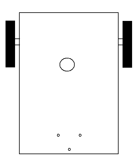
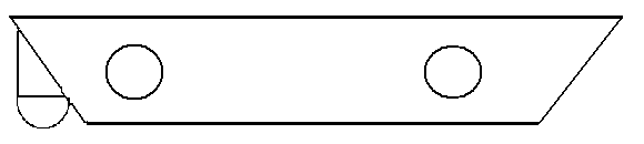
Before you start making your robot you need a paper plan. Measure length of the motor (excluding shaft), diameter of shaft of the motor, inner hole diameter of the motor. Draw a rough sketch of the base you need to cut keeping in mind the placement of motors and wheels.


Holes to fit caster wheel
Holes for wiring


TOP VIEW


Caster wheel
Holes to fit caster motor

SIDE VIEW


  1. Mechanical Assembly –  

Fit the caster wheel at position show in above diagram with 1.5-2 inches (approx.) screw. Fit the dc motor into the holes of chassis and couple the wheel by using screw or rubber tube.


Bolt is to fit outside of chassis

Coupling motors and wheels


  1. Remote Designing-

Before designing remote we have to learn basic movement of robot which is shown in following table.

Movements 

Motor1 (left)

Motor2(right)

For moving forward

Clockwise

Clockwise

For moving backward

Anticlockwise

Anticlockwise

For turning left

Off

Clockwise

For turning right

Clockwise

Off


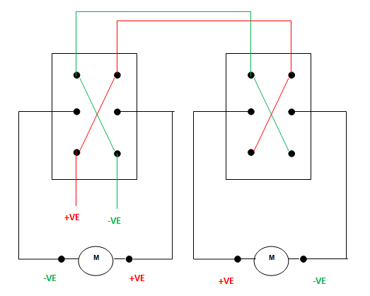
To make anti-clockwise motion of motor, the polarity of supply must be inverted of polarity of supply in clockwise motion. For "Polarity Reversal" DPDT switches are generally used. This can be done by using following circuit.


DPDT Switch Connections for REMOTE

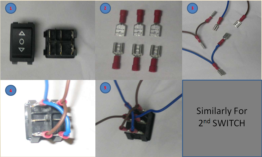
The wire should solder on metal strip not on switches directly (as shown in fig 3). This precaution helps us if there is wrong connection occurs in circuit. So we can change the circuit by changing metal strip position (fig 4). The procedure is shown in figure below-


DPDT Connections

4.  Motor connections-  

There are 4 output wires from remote which is to solder on motor by ribbon wire strip. Switch1's output should connect motor1 and switch 2's on motor2. This means switch1 controls motor 1 and switch 2 controls motor2. Before connecting motor by soldering, the polarity of motor should be check buy giving direct supplyfrom battery.


5. Power Supply-
The rechargeable battery of rating 9 Volt and 4.5 ampere rating should connected with remote switch (as shown in fig).

4. Speed calculation of robot-
Speed of robot can be calculate by following formula-
Velocity = circumference * rpm
Velocity = diameter * pi * rpm OR Velocity = 2 * radius * pi * rpm

The RPM of motor will perfect match with its specification if only is power rating of motor is provide by power supply.

Saturday, September 5, 2009

Parallel Port Monitoring Using MATLAB

MATLAB [!!Video Tutorial!!]


Hello friends , here is a small video tutorial on how to communicate to devices connected to our PCs parallel port using MATLAB programming. A large number of applications can be thought of using MATLAB as a platform in robotics. The digital bit data obtained at the parallel port can be utilized for driving DC motors or Stepper motors or other actuators.

%Code to transmit bits to the Parallel Port.
%The output1 & output2 matrix bits are transmitted sequentially.

parlport = digitalio('parallel', 'LPT1');
line = addline(parlport, 0:3, 'out');
output1 = [0 0 0 1; 0 0 1 1; 0 1 1 1; 1 1 1 1; 0 0 0 0];
output2 = [1 0 0 0; 1 1 0 0; 1 1 1 0; 1 1 1 1; 0 0 0 0];
for m=1:5
for x = 1:5
pval1 = output1(x,:);
putvalue (parlport, pval1);
pause(0.3);
end
for y = 1:5
pval2 = output2(y,:);
putvalue (parlport, pval2);
pause(0.3);
end
end

"Feel free to post your queries and doubts in the tutorial, I will try to upload some more video tutorials exploring MATLAB as a useful tool in Robotics".

Wednesday, August 12, 2009

LCD Interfacing with Atmega16

LCD Interfacing with Atmega16

LCD display:

The display used here is 16x2 LCD (Liquid Crystal Display); this means 16 characters per line by 2 lines. A very popular standard exists which allows us to communicate with the vast majority of LCDs regardless of their manufacturer. The standard is referred to as HD44780U, which refers to the controller chip which receives data from an external source (in this case, the Atmega16) and communicates directly with the LCD. The 44780 standard requires 3 control lines as well as either 4 or 8 I/O lines for the data bus. Here we are using 8-bit mode of LCD, i.e., using 8-bit data bus.

Image0040.jpg

The three control lines are referred to as EN, RS, and RW.

The EN line is called "Enable." This control line is used to tell the LCD that we are sending it data. To send data to the LCD, our program should make sure this line is low (0) and then set the other two control lines and/or put data on the data bus. When the other lines are completely ready, bring EN high (1) and wait for the minimum amount of time required by the LCD datasheet (this varies from LCD to LCD), and end by bringing it low (0) again.

The RS line is the "Register Select" line. When RS is low (0), the data is to be treated as a command or special instruction (such as clear screen, position cursor, etc.). When RS is high (1), the data being sent is text data which should be displayed on the screen. For example, to display the letter "T" on the screen you would set RS high.

The RW line is the "Read/Write" control line. When RW is low (0), the information on the data bus is being written to the LCD. When RW is high (1), the program is effectively querying (or reading) the LCD. Only one instruction ("Get LCD status") is a read command. All others are write commands--so RW will almost always be low.

In our case of an 8-bit data bus, the lines are referred to as DB0, DB1, DB2, DB3, DB4, DB5, DB6, and DB7.

Fig: 16X2 LCD display

Function

Pin Number

Name

Logic State

Description

Ground

1

Vss

-

0V

Power supply

2

Vdd

-

+5V

Contrast

3

Vee

-

0 - Vdd

Control of operating

4

RS

0
1

D0 – D7 are interpreted as commands
D0 – D7 are interpreted as data

5

R/W

0
1

Write data (from controller to LCD)
Read data (from LCD to controller)

6

E

0
1
From 1 to 0

Access to LCD disabled
Normal operating
Data/commands are transferred to LCD

Data / commands

7

D0

0/1

Bit 0 LSB

8

D1

0/1

Bit 1

9

D2

0/1

Bit 2

10

D3

0/1

Bit 3

11

D4

0/1

Bit 4

12

D5

0/1

Bit 5

13

D6

0/1

Bit 6

14

D7

0/1

Bit 7 MSB

Table: Pin description of LCD

LCD Circuit:

lcd1

To Pin 4,5,6 To PortA

Of PortD


Fig: LCD Connections

Testing (D.C. Conditions):

  • PIN 7 to 14 are data pins.
  • Voltage at pin 2 is +5.00V
  • Pin 3 is connected to 10K variable resistance for contrast setting.

  • Pin 4, 5, 6 are control lines connected to PORT D.

Actual circuit diagram is similar to the LCD connections in this CIRCUIT.

LCD Basic Commands:

No.

Instruction

Hex

Decimal

1

Function Set: 8-bit, 1 Line, 5x7 Dots

0x30

48

2

Function Set: 8-bit, 2 Line, 5x7 Dots

0x38

56

3

Function Set: 4-bit, 1 Line, 5x7 Dots

0x20

32

4

Function Set: 4-bit, 2 Line, 5x7 Dots

0x28

40

5

Entry Mode

0x06

6

6

Display off Cursor off
(clearing display without clearing DDRAM content)

0x08

8

7

Display on Cursor on

0x0E

14

8

Display on Cursor off

0x0C

12

9

Display on Cursor blinking

0x0F

15

10

Shift entire display left

0x18

24

12

Shift entire display right

0x1C

30

13

Move cursor left by one character

0x10

16

14

Move cursor right by one character

0x14

20

15

Clear Display (also clear DDRAM content)

0x01

1

16

Set DDRAM address or cursor position on display

0x80+add

128+add

17

Set CGRAM address or set pointer to CGRAM location

0x40+add

64+add

Programming Steps Sequence:

1) Initialize the LCD.

2) Select the command or instruction register (RS=0 or RS=1).

3) Set RW low (to write to LCD).

4) Send a high to low pulse on EN pin.

5) Check if the LCD is busy (Optional Step, it eliminates the delay issue).

6) Move to instruction or command function.

7) Repeat above steps.

The Source Code:

/*Every relevant command is included with a detailed and explanatory comment, if you still encounter any problem in the code feel free to post your queries*/

/* Platform: WINAVR*/

/*This code simply prints RoboZeal on LCD*/

#define F_CPU 12000000 //Change the F_CPU value to that you're using in your hardware, I used 12Mhz

#include <avr/io.h>

#include <util/delay. h>

#define dataport PORTA

#define commport PORTD

#define rs PD4

#define wr PD5

#define en PD6

int LCD_init(void);

int LCD_SendData(void);

int wrcomm(void);

int wrdata(void);

int main(void)

{

DDRA = 0xFF; //Set PortA as output port

DDRD = 0x70 //Set PortD 4, 5, 6 pin as output pins

LCD_init(); //Initialise LCD

LCD_SendData( ); //Write to LCD

return 1;

}

int LCD_init()

{

dataport = 0x38; //initialize LCD 2 lines, 5x7 matrix

wrcomm(); //Right the command byte to command register

dataport = 0x01; //Clear LCD

wrcomm(); //Right the command byte to command register

dataport = 0x0E; //Display on Cursor Blinking

wrcomm(); //Right the command byte to command register

dataport = 0x80; //Cursor at line 1, position 1

wrcomm(); //Right the command byte to command register

dataport = 0x1C; //Shift Entire Display To Right

wrcomm(); //Right the command byte to command register

return 1;

}

/*********** **** <<Sending Data To LCD Display>> ************ ***/

int LCD_SendData(void)

{

unsigned char j[] = "RoboZeal";

int i;

for(i = 0; i < sizeof j; i++)

{

dataport = j[i];

wrdata();

}

return 1;

}

/******* <<Righting the command byte to command register>> ********/

int wrcomm(void)

{

commport &= ~(1 << rs); //Setting RS = 0, selecting command register

commport &= ~(1 << wr); //Setting RW = 0

commport |= (1 << en); //EN = 1

commport &= ~(1 << en); //EN = 0, thus giving high to low pulse on Enable pin

_delay_ms(10); //10ms delay

return 1;

}

/********** <<Righting the Data byte to Data register>> **********/

int wrdata(void)

{

commport |= (1 << rs); //Setting RS = 1, selecting data register

commport &= ~(1 << wr); //Setting RW = 0

commport |= (1 << en); //EN = 1

commport &= ~(1 << en); //EN = 0, thus giving high to low pulse on Enable pin

_delay_ms(10) ; //10ms delay

return 1;

}

NOTE:

  1. Only one command that is “Get LCD status” is a read command all others are write command.

  1. The LCD interprets and executes our command at the instant the EN line is brought low. If you never bring EN low, your instruction will never be executed. Additionally, when you bring EN low and the LCD executes your instruction, it requires a certain amount of time to execute the command. The time it requires to execute an instruction depends on the instruction and the speed of the crystal which is attached to the 44780's oscillator input. (So watch the delay function in the code).

For Compiling & Burning the Program refer to: WinAVR for Parallel Port Programmer

For Building simple Parallel Port Programmer refer to: Programmer For Atmega 16/32

Regards:

Aditya Sharma

Robotics INDIA